

1.Introduction
With increasingly serious environmental pollution and energy crisis, people are getting more and more eager for new energy. Besides lithium ion batteries (LIBs) [1-3], lithium sulfur (Li-S) [4-6], lithium-air (Li-O2) [7-9] and Li-SeS2 [10,11], sodium ion batteries (SIBs) have also caught attention [12e17]. Among them, due to the rich reserves and low cost of sodium resources, SIBs is developing rapidly [12-17]. However, by comparison with LIBs, except for the similar work principle, SIBs present poor capacity performance because of the sluggish diffusion kinetics of Naþ ions induced by the larger Naþ ion radius (1.02 Å) than Liþ ion radius (0.76 Å) [12]. Moreover, the larger atomic weight and less negative potential of Na further lead to a lower energy density of SIBs. The two reasons slow down the practical process of SIBs. Therefore, researchers have been working hard to improve the performance of SIBs. As an important part of SIBs, cathode materials, such as layered transition metal oxides [18-20], ferrocyanides [21,22] and polyanionic compounds [23-32], have been paid great attention. Specially, NASICON sodium vanadium fluorophosphate (Na3V2(- PO4)2F3, NVPF), which can be considered as using three F- to replace one (PO4) 3- group, shows very interesting electrochemical performance [28-30]. Besides the inherent structural stability characteristic of polyanion materials, the NASICON structure also owns an open 3D framework with large interstitial spaces and is suitable for rapid diffusion of ions, which can improve the electrochemical kinetics of Naþ ions during the extraction/insertion process [26]. NVPF has a theoretical capacity of 128 mAh g-1 when two Naþ ions are reversibly extracted/intercalated from/into the NVPF structure. Compared with Na3V2(PO4)3 (NVP), NVPF also has an improved energy density due to the higher voltage platform induced by the stronger electronegativity of F- [29]. Interestingly, the valence state of vanadium plays an important role in electronic conductivity. For instance, the electronic conductivity of V2O3 is ~104 S cm-1 [33], while that of V2O5 is only ~10-6 S cm-1 [34]. In addition, W. He et al. also found heterogeneous valence states of V can cause a semiconducting behavior [35]. However, in NVPF, the valence state of V is þ3, but the separation of V atoms by PO4 tetrahedral leads to a low electronic conductivity, thus a poor capacity performance. Furthermore, the side reactions between NVPF and electrolyte during charge/discharge process lead to unsatisfied cycle performance. To our knowledge, introducing carbon materials [36-41] is an economic and feasible way to improve the electronic conductivity of materials; moreover the obtained carbon coating can protect active material from direct contact with electrolyte to a certain extent. But, the addition of excessive carbon may more or less decrease the tap density of electrode materials owing to the small density of carbon. Metal oxides own high ionic conductivity in spite of unsatisfactory electronic conductivity, and thus are often used to modify electrode materials [32e45]. Particularly, Al2O3, a superior sodium ionic conductivity, has been successfully applied as electrolyte membrane in sodium sulfur batteries and sodium metal halide batteries [46,47]. Additionally, Al2O3 has also been widely used to modify anode and cathode materials for LIBs and SIBs [48-55]. For instance, Y.S. Jung, G.H. Waller, H.R. Kou and et al. [50-52] applied atomic layer deposition (ALD) method to deposit Al2O3 coatings onto LiCoO2, LiMn2O4 and NiCo2O4, respectively, and found that besides acting as a mechanical barrier between electrode and electrolyte, the Al2O3 coatings can also reduce polarization of electrode reaction process due to its good ionic conductivity. In comparison with ALD, wet chemistry method is more economical, and the positive effect of Al2O3 coating on battery performance especially the cycle performance has also been confirmed by Y.H. Liu, H. Miyashiro, A. Friesen and et al. [54-56]. However, there is no report about Al2O3 coating for NVPF so far.
In this work, considering the good electronic conductivity of carbon and the superior sodium ionic conductivity of Al2O3, we used a wet chemistry method to fabricate carbon and aluminum oxide co-coated NVPF as cathode material for SIBs for the first time and investigated the effect of the hybrid layer coating of C and Al2O3 on the structure and electrochemical performance of NVPF. This composite exhibits significantly enhanced capacity performance and cycle stability compared with bare NVPF, carbon coated NVPF and Al2O3 coated NVPF. The co-coating layer can not only protect NVPF from direct contact with electrolyte and improve the structural stability, but also form effectively conductive network to facilitate the electron/ion transmission and thus improve the capacity performance.
2.Experimental
2.1. Synthesis of Na3V2(PO4)2F3 composites
The four Na3V2(PO4)2F3 (NVPF) composites were prepared by using oxalic acid, V2O5, NH4H2PO4 and NaF as raw materials in a molar ratio of 4.5: 1: 2: 3 via wet chemistry method. The preparation procedure of carbon coated NVFP is described in detail as follows: oxalic acid was first dissolved in deionized water under magnetic stirring at 60 ℃. Then, V2O5 was added and constantly stirred to get a blue solution. Subsequently, stoichiometric amount of NH4H2PO4 and NaF was added to the above solution and kept on stirring until a blue gel was formed. After drying at 80 ℃ for 24 h, the blue gel was pre-heated at 350 ℃ for 6 h in N2. Then, appropriate amount of glucose was added and ball milled for 2 h in ethanol. Finally, the mixture was sintered at 700 ℃ for 10 h in N2, and then cooled down slowly to achieve the carbon coated NVPF composites (labeled as NVPF/C). The bare NVPF composite was synthesized via the similar route without glucose (donated as NVPF). The aluminum oxide coated NVPF (abbreviated as NVPF/Al) and carbon and aluminum oxide co-coated NVPF (abbreviated as NVPF/C-Al) were synthesized according to the following procedure: 1 g NVPF (or NVPF/C) was dispersed in 100 ml deionized water by ultrasonication for 40 min to get a suspension, then a certain amount of Al(NO3)3·9H2O was added and mixed by ultrasonic dispersion for 30 min, then constantly stirred for 20 min to form a black solution at room temperature. Subsequently, appropriate dosage of NH3·H2O was slowly dropped into the black suspension with continuously stirring at 60 ℃. After 1.5 h, the precipitate was collected by filtration, washed several times with deionized water, and then dried at 60 ℃ in oven for 12 h. Finally, the powder was sintered at 600 ℃ for 2 h in N2 atmosphere to obtain NVPF/Al (or NVPF/C-Al).
2.2. Materials characterization
The crystal structure and phase of samples were examined by Xray powder diffraction (XRD, D8 Advance, Bruker, Germany) with CuKa radiation, and the diffraction data was recorded in a 2q range of 10-80° at a scanning rate of 8° min-1 . The morphology was observed by both a field emission scanning electron microscopy (FESEM, JSM-7500F, JEOL, Japan) and a high resolution transmission electron microscope (HRTEM, Talos F200S, Thermo Fisher, US). The elemental analysis was conducted on an X-ray photoelectron spectroscopy (XPS, PHI QuanteraII, Japan). The carbon content and electronic conductivity of samples were respectively determined by carbon-sulfur analyzer (CS600, LECO, US) and a powder resistivity measurement system (FT-300I, Rico, China). The Al content in the NVPF/Al and NVPF/C-Al composites were measured by a UVeVis spectrophotometer (UV-9100, Ruili, China).
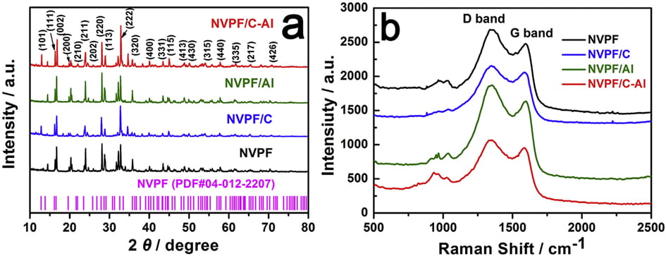
Fig. 1. (a) XRD patterns, and (b) Raman spectra of NVPF, NVPF/C, NVPF/Al and NVPF/C-Al.
2.3. Electrochemical performance tests
The working electrodes were prepared by mixing active material (such as NVPF, NVPF/C, NVPF/Al and NVPF/C-Al) with acetylene black conductor and PVDF binder in a weight ratio of 75:15:10. The mixture was stirred for 12 h and then pasted on Al foil substrate to obtain a uniform film. After drying, the obtained film was punched into discs with diameter of 14 mm and then pressed at a pressure of ~6 MPa. Finally, the discs (the loading mass of active material is about 1.5 mg cm-2 ) were dried at 120 ℃ for 8 h in vacuum oven for battery assembly. The R2025 coin cells were assembled by using whatman glass fiber as separator, metallic sodium foil as counter electrode, and 1.0 M NaClO4 in EC:DMC:EMC ¼ 1:1:1 with 2 vol % FEC as electrolyte. Galvanostatic charge/discharge measurements were carried out in the voltage range of 3.0e4.6 V by using the multichannel cell test system (LAND CT2001A, China). Cyclic voltammetry (CV) tests at the voltage range from 3.0 to 4.6 V and electrochemical impedance spectroscopy (EIS) tests at the frequency range of 0.01 Hze100 kHz were both performed on the electrochemical workshop (CHI614C, China).

Fig. 2. SEM and HRTEM images of samples: (a1,a2,a3) NVPF, (b1,b2,b3) NVPF/C, (c1,c2,c3) NVPF/Al, and (d1,d2,d3) NVPF/C-Al.
3.Results and discussion
Fig. 1a shows the XRD patterns of the bare NVPF, NVPF/C, NVPF/ Al and NVPF/C-Al composites. Just like the main diffraction peaks of NVPF and NVPF/C, those of NVPF/Al and NVPF/C-Al composites can also be well indexed to standard Na3V2(PO4)2F3 phase and also be in good agreement with previous reports [57,58], which indicates that Al-introducing does not change the NASICON structure of Na3V2(- PO4)2F3. It’s worth mentioning that, besides the absence of diffraction peaks of crystalline carbon in NVPF/Al and NVPF/C-Al as well as in NVPF and NVPF/C, the diffraction peaks of Al-containing composites are also not observed
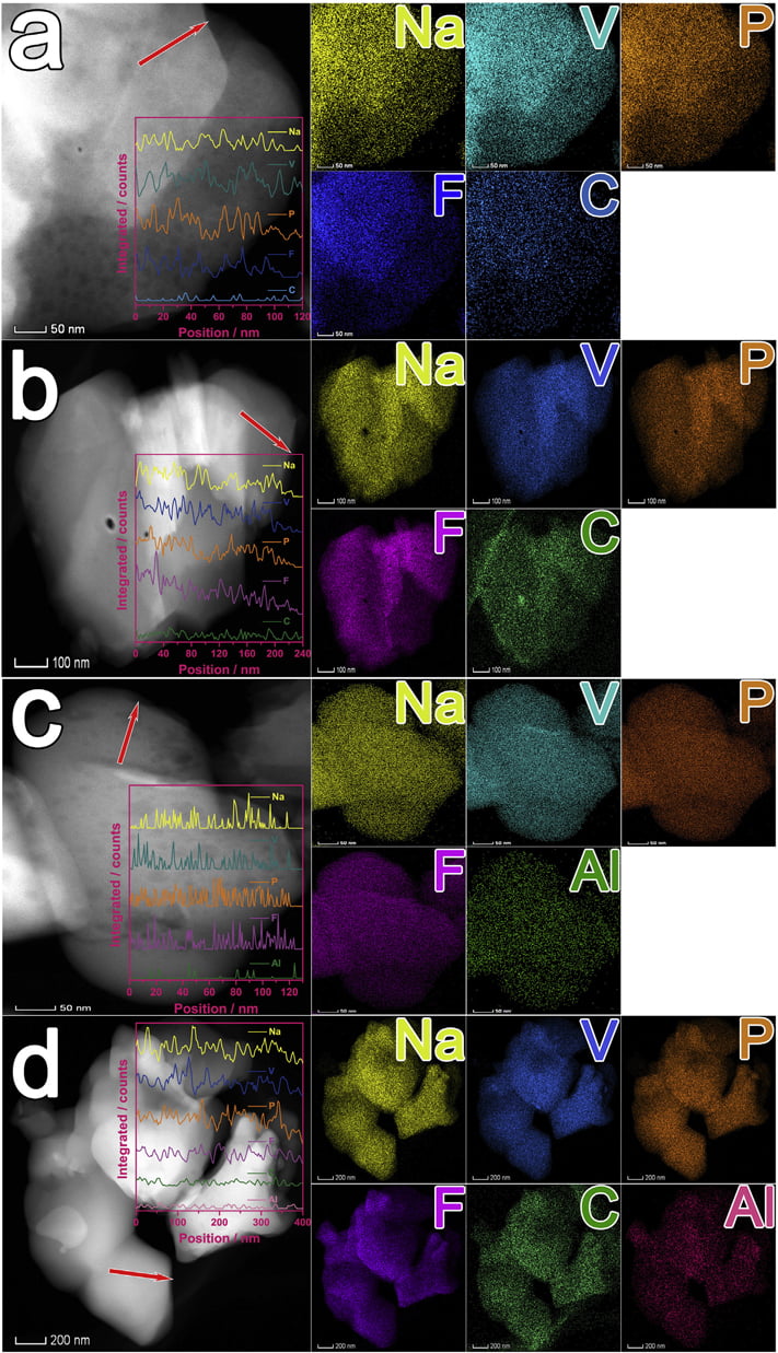
Fig. 3. HAADF images, EDS line scan spectra and mappings of samples: (a) NVPF, (b) NVPF/C, (c) NVPF/Al, and (d) NVPF/C-Al.
in the XRD patterns of NVPF/Al and NVPF/C-Al, suggesting that C and Al elements in samples exist in the form of amorphous or have low contents (Table 1). In order to investigate the residual carbon structure, Raman measurements of four samples were performed. As shown in Fig. 1b, the characteristic Raman signatures located at ~1351 and ~1591 cm-1 correspond to the D and G bands of carbonaceous materials, respectively. As we known, the relatively intensity ratio of D and G bands (ID/IG) reflects the graphitization degree of carbon [3,59]. As listed in Table 2, NVPF/C-Al (1.928) exhibits obviously lower ID/IG value than NVPF/C (1.973), and NVPF/Al (1.952) also owns lower ID/IG value than NVPF (2.001). That is to say, the two Al-incorporated samples such as NVPF/Al and NVPF/C-Al both have lower ID/IG value than NVPF and NVPF/C, which demonstrates that Al-introducing is helpful for promoting graphitization of residual carbon in samples, thus leading to an enhanced electronic conductivity. So, though the electronic conductivity of Al2O3 is not as good as carbon, the electronic conductivity of NVPF can be still improved by Alincorporating. As listed in Table 1, the two Al-incorporated samples such as NVPF/Al and NVPF/C-Al respectively exhibit higher electronic conductivity than NVPF and NVPF/C. Of course, compared with NVPF and NVPF/Al, the two carbon-coated NVPF samples such as NVPF/C and NVPF/C-Al powders respectively show better electronic conductivity because of the effect of conducting carbon. Especially, under the common effect of carbon and Al2O3, the NVPF/C-Al sample exhibits the best electronic conductivity.
The morphology of the bare NVPF, NVPF/C, NVPF/Al and NVPF/ C-Al samples was characterized by both SEM and HRTEM measurements (as shown in Fig. 2). Compared with NVPF and NVPF/Al (Fig. 2a1 and c1), the NVPF/C and NVPF/C-Al powders exhibit much less agglomeration (Fig. 2b1 and d1), which indicates that carbon can effectively reduce the adhesion between these NVPF particles. As displayed in the HRTEM images of the NVPF, NVPF/C, NVPF/Al and NVPF/C-Al composites (Fig. 2a3, b3, c3 and d3), it can be clearly seen that, except for bare NVPF (Fig. 2a3), the NVPF/C (Fig. 2b3), NVPF/Al (Fig. 2c3) and NVPF/C-Al (Fig. 2d3) particles are covered with uniform thin amorphous layer. These coating layers can to a certain extent protect NVPF active material from direct contact with electrolyte and restrain side reaction, thus improve the structural stability. In addition, NVPF, NVPF/C, NVPF/Al and NVPF/C-Al all exhibit obvious lattice fringes, i.e., the interplanar spacing of 0.304, 0.336, 0.348 and 0.547 nm corresponds to the (221), (103), (202) and (111) planes of NVPF, respectively, which reflects the good crystallinity for the four composites.
To investigate the distribution of C, Al, Na, V, P and F elements, HAADF images, EDS line scan spectra and mappings of NVPF, NVPF/ C, NVPF/Al and NVPF/C-Al are displayed in Fig. 3. From the mappings of the four samples, it can be clearly seen that C or/and Al as well as Na, V, P and F elements are uniformly distributed in the NVPF, NVPF/C, NVPF/Al and NVPF/C-Al samples. Moreover, the EDS line scan spectra (the insert in the corresponding HAADF images)
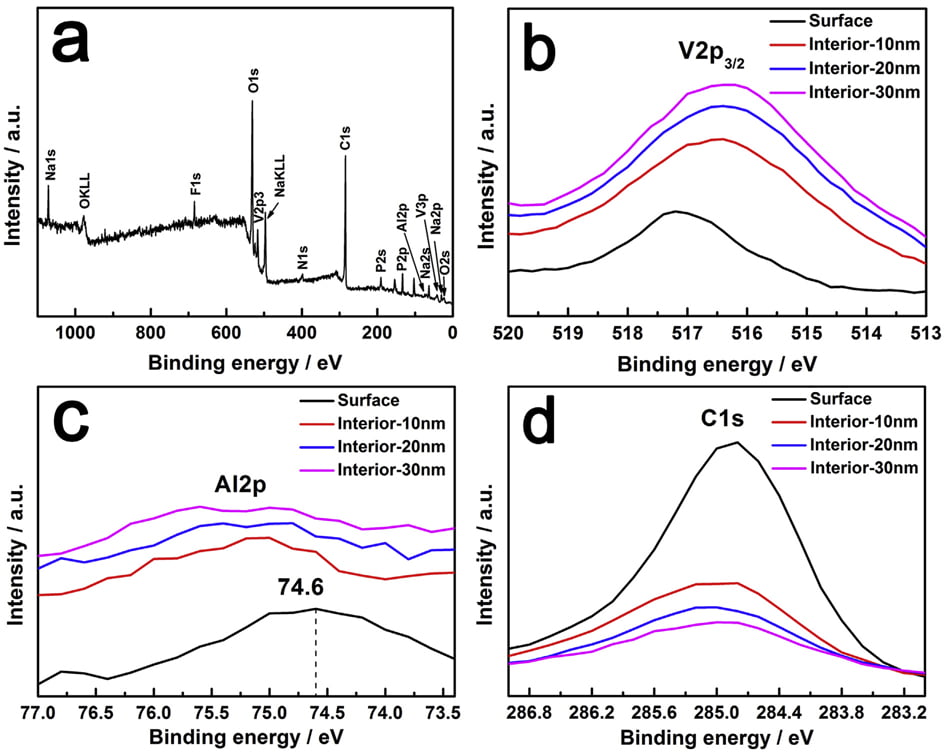
Fig. 4. XPS spectra of NVPF/C-Al powders: (a) full spectrum, (bed) core-level spectra of V2p3/2, Al2p and C1s.
show that, the intensity of C or/and Al is apparently lower than that of Na, V, P and F due to their low content in the samples, but the distribution of C or/and Al is similar to Na, V, P and F, which further confirm the homogeneously distribution of C and Al as well as Na, V, P and F.
XPS measurements were carried out to analyze the valence of the key elements in NVPF/C-Al composite, and Ar ions sputtering technology was also applied to study the existence position of C and Al elements. The data of different depths from surface to inside (10, 20 and 30 nm) were also collected. As shown in the full XPS spectrum (Fig. 4a), it is clear that, besides the basic elements of Na, V, P, O and F, the C and Al elements also appear. It should be noted that, considering the chemical reduction of Ar ions, we use the spectra before sputtering to analyze the valence of elements. According to W. He’s report, the V2p3/2 peak at ~517.2 eV is ascribed to V5þ [60]. However, due to the effect of coordination environment, for the NVPF/C-Al composite, as shown in Fig. 4b, the binding energy of ~517.2 eV for the V2p3/2 peak represents the oxide state of þ3 [35,61e63]. This result indicates that C and Al incorporation does not affect the valence of V3þ in NVPF molecule. The Al2p peak at ~74.6 eV displayed in Fig. 4c (black line) corresponds to the valence of Al3þ ions in Al2O3 [51]. As seen in Fig. 4c and d, the peak intensities of Al2p and C1s on the surface are much stronger than those in the interior, and with the increase of sputtering depth, the peak intensity decreases gradually. These observations demonstrate that C and Al2O3 are coated on the surface of the NVPF particles, which further reveals that the amorphous hybrid layer observed in the HRTEM image of NVPF/C-Al (Fig. 2d3) is composed of C and Al2O3. We can also infer the amorphous layer on the surface of NVPF/C is C, and the amorphous layer on NVPF/Al is Al2O3.
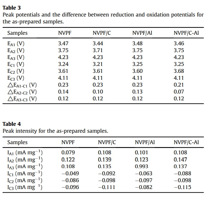
In order to evaluate the effect of C and Al2O3 coating on the electrochemical behavior of NVPF cathode material for SIBs, cyclic voltammogram (CV) tests were performed at a scanning rate of 0.1 mV s-1 in the voltage range of 3.0e4.6 V. As shown in Fig. 5, all the four CV curves exhibit three pairs of sharp redox peaks located at about 3.47/3.24, 3.75/3.61 and 4.23/4.11 V, respectively. For instance, the first two redox peaks correspond to a two-step extraction/re-insertion process of the first Naþ ions from/into the Na(2) sites, and the third redox peaks at a higher voltage of ~4.23/ 4.11 V are related to the extraction/re-insertion of the second Naþ ions from/into the Na(1) sites [31,58]. As listed in Tables 3 and 4, by comparison, both NVPF/C and NVPF/C-Al show smaller redox potential difference and higher peak intensity, especially NVPF/C-Al owns the smallest redox potential difference and the closest peak intensity of the oxidation peaks and the reduction peaks, indicative of the least polarization and the best reversibility for NVPF/C-Al.
Galvanostatic charge/discharge measurements were also carried out to evaluate the capacity performance of samples. Fig. 6a shows the initial charge/discharge profiles of the four samples in the voltage range of 3.0e4.6 V at 1 C (1 C equals to a current density of 128 mA g-1 ). All the samples display three characteristic plateaus of NVPF, corresponding to the redox peaks in the CV curves (Fig. 5). Compared with NVPF (96.4 mAh g-1 ), NVPF/C (107.5 mAh g-1 ) and NVPF/Al (100.8 mAh g-1 ), the NVPF/C-Al electrode delivers the highest initial capacity of 128.4 mAh g-1 , which is also slightly higher than the theoretical value of 128 mAh g-1
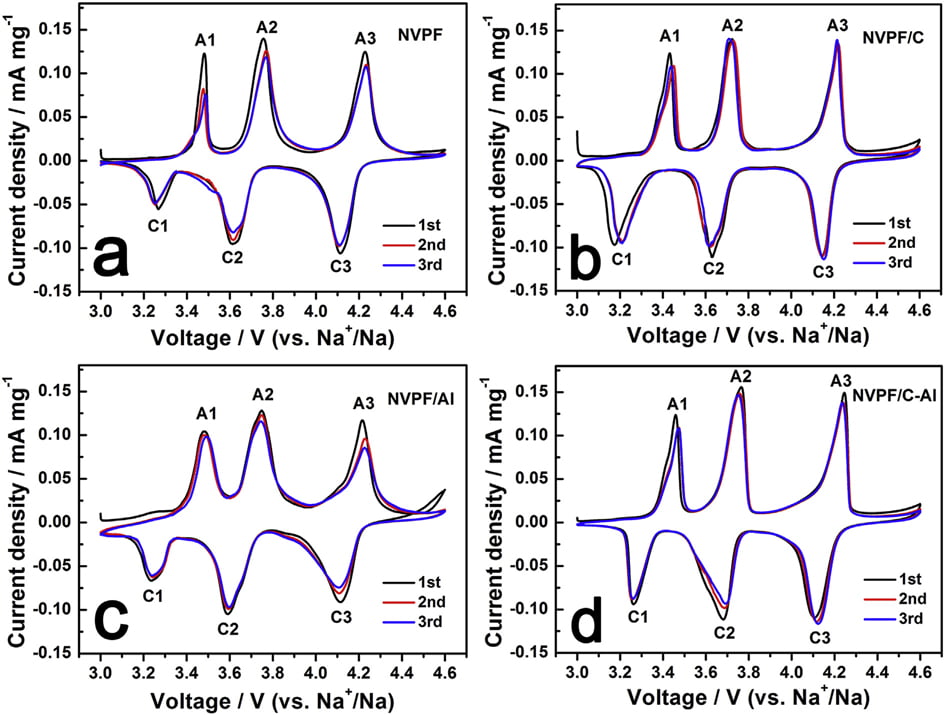
Fig. 5. CV curves of samples for the first three cycles: (a) NVPF, (b) NVPF/C, (c) NVPF/Al, and (d) NVPF/C-Al.
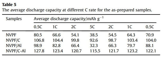
due to the surfaceand/or interface sodium storage [64]. Moreover, as shown in Fig. 6b, after 100 cycles at 1 C, NVPF/C-Al still retains the highest capacity of 122.8 mAh g-1 with a superior capacity retention ratio of 95.6%, whereas NVPF/C, NVPF/Al and NVPF only respectively exhibit capacity as low as 97.9, 74.5 and 66.7 mAh g-1 with a capacity retention ratio of 91.1, 73.9 and 69.2%. The rate performance of the four samples at different C rates is also shown in Fig. 6c. For each sample, when the C-rate is back from 5 C to 0.5 C, the capacity can also be recovered well, suggesting an excellent tolerance of experiencing between varied C rates for each electrode. Furthermore, with increasing C rate, the discharge capacity decreases, which demonstrate that the extraction/re-insertion of Naþ ions is controlled by ion diffusion. Nevertheless, compared with NVPF, NVPF/C and NVPF/Al, the NVPF/C-Al electrode still exhibits the highest average discharge capacity, i.e., 127.8, 123.4, 120.7, and 115.5 mAh g-1 at 0.5, 1, 2 and 5 C, respectively (shown in Table 5). To investigate the structural stability, XRD measurements of the four electrodes after 100 cycles at 1 C were performed. Compared the XRD patterns after cycle in Fig. 6d with those before cycle in Fig. 1a, there are some difference in the diffraction peak intensity, but, apart from two strong diffraction peaks ascribed to Al foil current collector, the main diffraction peaks of NVPF
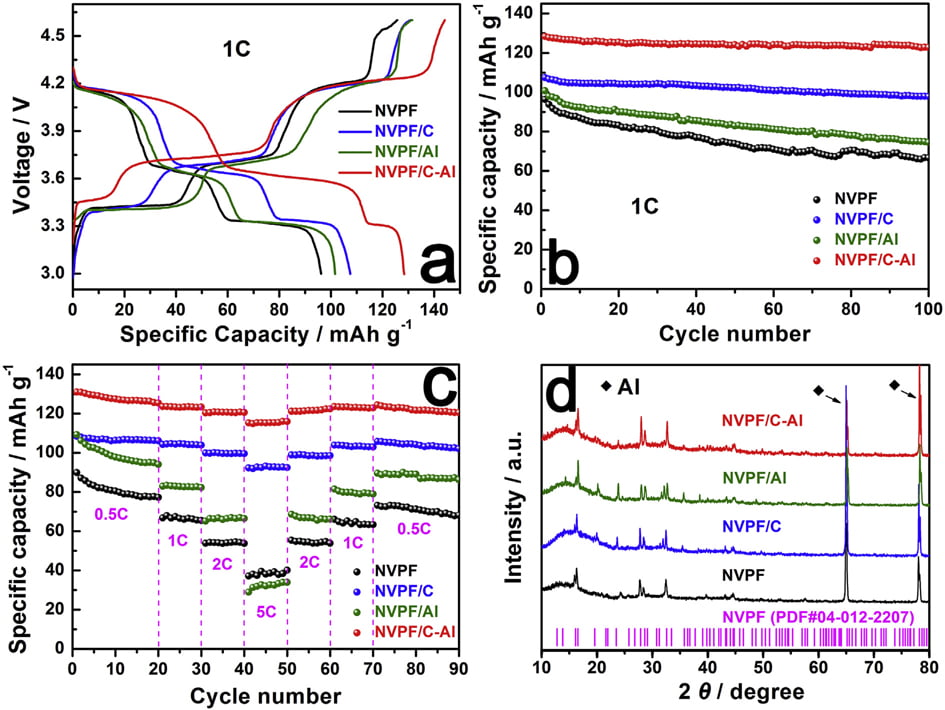
Fig. 6. (a,b) The initial charge/discharge profiles and the corresponding cycle performance at 1 C, (c) the rate performance at different rates, and (d) XRD patterns of NVPF, NVPF/C, NVPF/Al and NVPF/C-Al after 100 cycles.
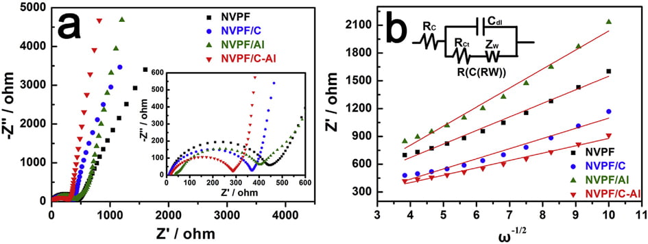
Fig. 7. (a) EIS curves, and (b) the relationship lines between Z0 and u-1/2 in the low frequency region of samples.
phase (JCPDS No. 04-012-2207) can still be detected. Moreover, compared with NVPF, NVPF/C and NVPF/Al, the NVPF/C-Al electrode has the sharpest diffraction peaks, which indicates that NVPF/C-Al has the most stable structure after cycle. The stable structure of NVPF/C-Al can be explained by that the hybrid coating of C and Al2O3 can protect NVPF from direct contact with electrolyte more effectively and restrain side reaction, which may lead to an enhanced cycle performance.
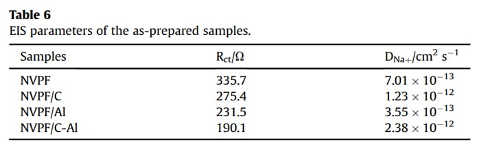
EIS measurements were conducted to investigate the role of Al2O3 coating on the electrochemical performance of NVPF/C. As shown in Fig. 7a, all the EIS spectra are comprised of an intercept at high frequency region, a semicircle at medium frequency region and a sloping line at low frequency region. All the EIS data were fitted with an equivalent circuit of “R(C(RW))” (the insert in Fig. 7b) by the ZSimpWin program [3,17,40]. In the EIS spectra, the intercept corresponds to the Ohmic resistance of the cell (Rc), the semicircle represents the charge transfer resistance (Rct), and the sloping line reflects the Warburg impedance (Zw) related to sodium ions diffusion within electrode. The fitted values of Rct and Naþ ions diffusion coefficient (DNaþ) are listed in Table 6. Obviously, after coating (i.e., single C coating, Al2O3 coating or hybrid coating of C and Al2O3), the Rct value decreases and the DNaþ value increases. In particular, the NVPF/C-Al electrode shows the lowest Rct (190.1 U) and the highest DNaþ (2.38 ×10⁻¹² cm2 s -1 ). The decreased charge transfer resistance and increased Naþ ions diffusion coefficient are ascribed to the effectively electron/ion conductive network caused by the hybrid coating layer, which may result in an improved capacity performance.
4.Conclusions
In summary, carbon and aluminum oxide co-coated Na3V2(- PO4)2F3 composite was successfully synthesized via a wet chemistry method and the effect of the hybrid layer coating on the electrochemical performance of NVPF cathode material for sodium ion batteries was also investigated. Compared to bare NVPF, Ccoated NVPF and Al2O3-coated NVPF, the C and Al2O3 co-coated NVPF exhibits the highest reversible capacity and the best cycling stability. C and Al2O3 layer co-coated on the surface of NVPF particles can effectively protect NVPF from direct contact with electrolyte and improve the cycle performance; meanwhile this hybrid coating layer can form effectively electron/ion conductive network and enhance the capacity performance. Therefore, this surface modification of C combined with Al2O3 was an effective way to improve the electrochemical performance of NVPF.
Acknowledgements
This work was supported by the National Natural Science Foundation of China (51572151, 51772169, 51672158), the National Key R&D Program of China (2018YFB0905400), the Outstanding Youth Science and Technology Innovation Team Project of Hubei Educational Committee (T201603), and in part by a FRC research grant of Sam Houston State University.