
I. Introduction
For future large-scale cost-effective stationary energy storage needs, high-temperature sodium batteries are promising candidates owing to their high energy density, zero self-discharge rate, 100 % faradaic efficiency in discharge and recharge, proven long-term reliability, and the use of abundant low-cost raw materials 1–2. The solid electrolyte is often configured as a tubular, thin-walled ceramic formed from ion-conductive Na beta″-alumina, a non-stoichiometric sodium aluminate stabilized by the incorporation of Li or Mg 3. This is a key component for cell performance, requiring optimisation of microstructure and phase purity to ensure good electrical and mechanical properties.
State-of-the-art manufacturing methods for producing β”-alumina solid electrolytes include isostatic pressing 4 and electrophoretic deposition (EPD) 5. Both are batch processes requiring numerous process steps that contribute significantly to battery cost. For large-volume production it would be desirable to identify a simplified low-cost continuous process. Extrusion offers this potential, but requires special development for adaptation to solid electrolyte production, including the selection of compatible binders, kneading with extrudable shear thinning rheology, and the design of dies with the required geometry including means of forming closed-end tubes 6–8.
Some efforts had been made previously to extrude beta″-alumina, but the paste formulation was complex 9 and over the years, little attempt seems to have been made to develop the process further. We have taken a fresh look at extrusion of β”-alumina, starting from relatively simple paste formulations, non-aqueous and aqueous, with the aim of achieving a streamlined process with few process steps. This paper will describe the challenges of achieving an extrusion paste formulation with suitable consistency and rheology, and discuss briefly other important issues such as die design, post-extrusion drying and handling, and sintering. Good results have been achieved with a solvent-based process starting with preconverted beta″-alumina; the ideal of an aqueous process with commercial raw materials needs further development.
II. Experimental Procedure
(1) Paste preparation
A homogeneous extrudable paste was formed by kneading in a high-shear vacuum Z-blade mixer (Werner & Pfleiderer mixer, ZD 224s) by adding binders to the powder mixtures. The kneading process required 1 – 2 hours duration to ensure homogeneous mixing of the binder in the paste. The paste rheology properties were measured using a capillary extrusion rheometer.
Two sources of raw material powder were investigated:
(A) A sodium beta alumina/zirconia powder mixture, containing an equal mixture of β-and β”-alumina phases, to which a proportion of zirconium oxide had been added.
(B) A precursor mixture of commercially available raw powders with the chemical formulation corresponding to the composition of sodium β” alumina was prepared. The starting powders were 72.7 wt% aluminium oxide (a-Al2O3 < 1.0 µm), 17.3 wt% sodium oxalate and 10.0 wt% lithium carbonate. The powders were drymilled together using zirconia balls for 1 hour.
In the following text, processes based on these starting materials are referred to as methods A and B respectively. For both methods the β”-alumina stabilizer was Li and the proportion of ZrO2 included was 6 % by weight. The rationale for including ZrO2 is described in §II(4). For method B, 6 wt% zirconium oxide (Mel Chemicals 3Y) was wet-milled separately in amyl alcohol for 3 hours to a predetermined particle size prior to addition to the remaining powders.
Two sets of binder/additives systems were used in paste formulations, one was solvent-based and the other was water-based. In general, method A was more successful with the solvent-based paste while method B was more successful with the aqueous paste; however, all permutations were investigated. The solvent-based paste consisted of 77.8 wt% powder, 7.8 wt% polyvinylbutyral, 0.25 wt% stearic acid, 0.4 wt% linseed oil and 13.75 wt% cyclohexanone. The aqueous paste consisted of 85.5 wt% powder, 2.5 wt% hydroxypropyl methyl cellulose, 0.6 wt% stearic acid and 11.4 wt% deionized water.
(2) Tube extrusion, drying and sintering
Conventional die designs for the extruder were found to be insufficiently robust to handle the stiff paste under the high extruding pressure. A special die was designed by the University of Birmingham, containing eight wellseparated holes measuring 9 mm in diameter, Fig. 1.
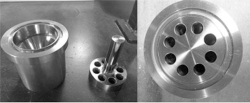
Fig. 1: Die design for open-ended tube extrusion.
The paste was extruded using a Loomis 232 – 16-DT Extruder at an extrusion rate of 20 mm/min, to form openended green tubes with a diameter of 18 mm and a wall thickness of 1 mm.
In the as-extruded state, the green tubes were wet and prone to distortion by gravity and handling. A post-extrusion handling and drying system to support the weight and shape of the wet tube was necessary in order to obtain a straight defect-free dry green tube. During the overnight drying step, the green tube was rolled with an oscillating motion in an attempt to maintain tube straightness and eliminate distortion of the tube cross-section from circular to oval.
During the single-firing cycle the tube was enclosed within magnesia crucibles to maintain sodium oxide vapour pressure at the high sintering temperature of 1650 °C for 15 minutes. Prior to sintering, burn-off of the binders was carried out by heating at 1000 °C for 3 hours.
(3) Characterization
Phase purity and microstructure of the sintered shape were analysed by means of X-ray diffraction and scanning electron microscopy (SEM) with energy-dispersive X-ray spectroscopy (Philips XL-30 FEG Environmental SEM with Oxford Inca EDS). Porosity was determined by measuring density measurement with the Archimedes technique. Axial ionic conductivity (along the length of the tube) was measured over the temperature range 25 – 600 °C using an AC 4-terminal method with platinum electrodes.
Radial ionic conductivity (through the tube wall) was measured in a Na/β”-alumina/NaNO2 test cell, the electrochemically active section of which is shown in Fig. 2. A beta″-alumina tube of length 60 mm was closed by glass joining at the bottom end to an alumina disc and at the top end to a 300-mm-length alumina tube. An aluminum tube formed the central sodium anode current collector, sealed to the alumina tube by silicone rubber, and connected to a vacuum system so that the inner (sodium) compartment could be evacuated and back-filled with nitrogen. The β”-alumina tube was immersed fully in molten NaNO2. The voltage across the beta″-alumina tube was measured between a nickel wire wrapped around the tube and the aluminium current collector. The radial conductivity cell is more representative than the axial measurement of conditions encountered in sodium battery cell applications, but is more prone to variability due to interfacial resistance complications resulting from non-wetting, impurities and other factor.
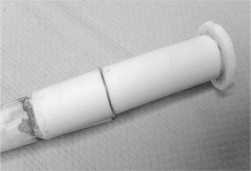
Fig. 2: β”-alumina tube assembly for radial conductivity measurement.
(4) The incorporation of zirconia into beta″-alumina
For the purposes of the present investigation, the main purpose of introducing ZrO2 into the ceramic to form a composite was that ZrO2 is an effective sintering aid, occasioned by the likely formation of a sodium zirconate eutectic and thereby promoting liquid phase sintering. This was particularly beneficial in the case of method B, which entailed a reaction sintering process and for which the achievement of near-theoretical density proved to be more challenging than for method A.
There are in addition other motives for the use of ZrO2/β”-alumina composites as solid electrolytes. Impurities in beta″-alumina ceramics, in particular calcium, can cause serious resistance degradation in electrochemical cells, and ZrO2 is an effective scavenger for Ca. At reasonably low levels of addition (< 10 % by weight), ZrO2 can result in a slight lowering in resistivity, not an increase as would be expected since at most battery temperatures of interest (∼ 300 °C) ZrO2 is an insulator. In addition the presence of ZrO2 phase prevents uncontrolled secondary grain growth during sintering, thereby resulting in improved mechanical strength, Weibull factor and toughness. Composite ceramic solid electrolytes have shown excellent durability and low failure rate in NaS electrochemical cells 10.
Regardless of the forming process to obtain the green shape, it is essential that the ZrO2 phase should be well dispersed within the β”-alumina matrix. In order to achieve a fine dispersion of the ZrO2 particles, a separate wet-milling process was required for method B. Particle size and SEM analysis showed a strong correlation between ZrO2 particle size and grain size control. Unmilled ZrO2 (Fig. 3a) showed some large particles of up to 100 lm, and in the sintered ceramic exaggerated grain growth was observed. With milled ZrO2 (Fig. 3b), a more uniform particle size was achieved and grain size in the sintered ceramic was limited to a maximum of 10 lm.
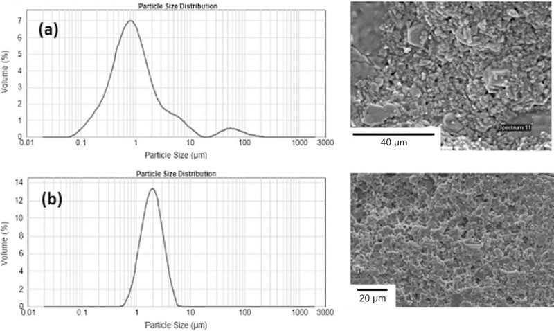
Fig. 3: Zirconia particle size distribution and corresponding sintered ceramic microstructure by SEM (a) unmilled (b) milled.
III. Results and Discussion
(1) Visual quality and dimensional aspects
Fig. 4 (a) and (b) shows sintered tubes from methods A and B, respectively. For method A, good quality straight tubes were obtained of length up to 300 mm or more. Method B presented more difficulties in achieving good extrudable paste quality and the resulting sintered tubes showed more deviation in straightness and cross-section, suggesting the need for further process optimisation.
(2) Ceramic phase purity
Extruded and sintered samples from both methods A and B showed a high proportion (> 98 %) β”-alumina phase in the β/β” phase, as required for high Na+ conductivity.
(3) Ceramic density
The density of ceramics obtained from method A was 98.6 % theoretical (TD), while those from method B showed 96.3 % TD. The lower density with method B may be associated with the need for reaction sintering of the unconverted raw powders, whereas for method A the starting powder was already preconverted to β/β”-alumina.
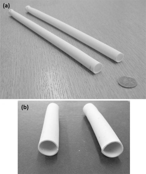
Fig. 4: Sintered tubes obtained with (a) method A and (b) method B.
(4) Ionic conductivity
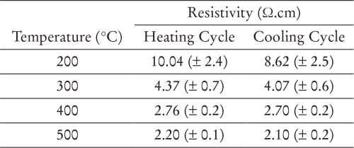
Extruded beta″-alumina/ZrO2 tubes obtained with method A showed reproducible axial resistivity over the range 20 – 500 °C (Table 1 and Fig. 5). At 300 °C the resistivity was 4.37 ± 0.70 X⋅cm, comparable to the average value of 4.46 ± 0.63 X⋅cm observed for tubes of the same composition produced with Ionotec’s production process based on EPD 11.
Table 1: Axial resistivity of sintered β”-alumina tubes.
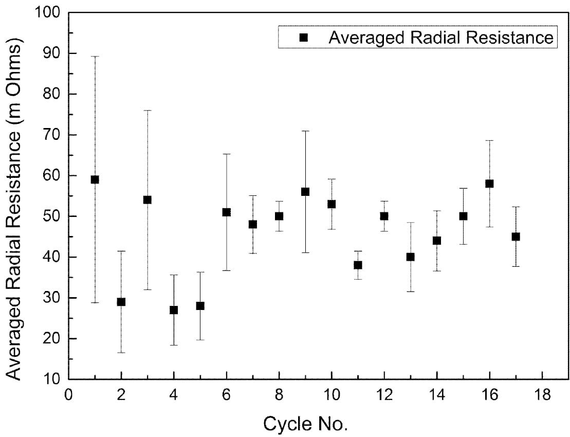
The radical conductivity cell (§II(3), Fig. 2) operated successfully for 18 full charge and discharge cycles but with more scatter in resistance measurements (Fig. 6). On cycle 9 the cell charge and discharge capacity at a rate of 1.17 A was 3.82 Ah and 3.17 Ah respectively (Fig. 7). The accumulated capacity was respectively + 41.75 Ah and – 37.63 Ah. From data on the minimum resistance observed during cycling, the ceramic resistivity is 5.7 X⋅cm at 300 °C. For tubes produced with EPD, the same measurement technique resulted in 4.7 X⋅cm, close to the result for axial resistivity. The higher radial resistivity for the extruded tube may represent either a degree of texture (preferred crystallite orientation) in the ceramic microstructure, or variability in wetting behaviour between the ceramic and liquid sodium at 300 °C.
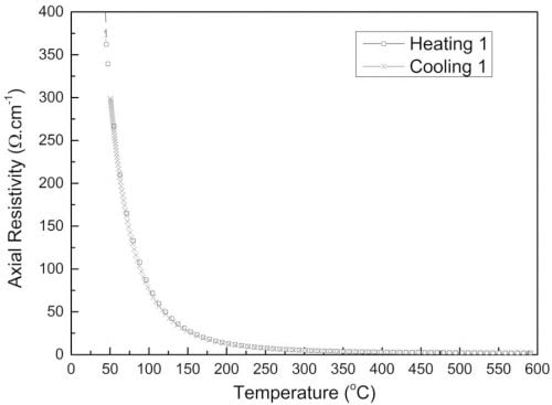
Fig. 5: Axial resistivity of an extruded β”-alumina tube.
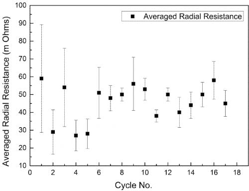
Fig. 6: Average radial resistance of an extruded β”-alumina tube over 18 cycles.
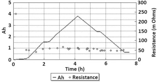
Fig. 7: Axial resistance and capacity of the Na/β”-alumina/NaNO2 cell, cycle 9.
IV. Summary and Conclusions
Straight thin-walled ZrO2/β”-alumina tubes can be produced by extrusion with acceptable ceramic quality for use as solid electrolytes in electrochemical cells. Tubes produced from preconverted β/β”-alumina/ZrO2 powder show properties similar to those produced with the EPD process. Those produced from unreacted precursor powders require further process development to achieve the standard achieved with preconverted powders, although the latter process has greater potential for significantly lower manufacturing costs.