

The non-aqueous redox flow battery (N-ARFB) is in the development stages with the strong potential for high power density (>2 V) N-ARFB that can store energy from non-conventional sources, such as wind mills and solar power.1 Although the development of N-ARFBs has attracted considerable interest, such as redox active species selection,2 electrolyte development,2,3 and solvent selection,4 the identification of a suitable membrane is one of the crucial factors because of the crossover of redox active species.4–6 The oxidation state of most redox active metal organic complexes (RAMOCs) is negative, which means that there is theoretically less migration on membranes with the same polarity but the transport of oppositely charged negative ions is allowed. Using this approach, many anionic selective polymeric membranes (AEM) were developed and made commercially available for N-ARFBs, such as Neosepta AHA (Astom, Japan), FAP4 (FuMa-Tech Co.), and AMI-7001 (Membrane International Inc., USA), which were investigated in N-ARFB systems using a conventional H-type cell.7–9 On the other hand, they showed poor chemical and mechanical stability in organic electrolytes.1 Through a zero-gap (electrodes coated on the membrane) redox flow battery prototype design, the modified Nafion 1035 membrane could be operated in all VRFB with columbic and energy efficiencies of 91% and 80%, respectively.10 A polymeric membrane prepared by a simultaneous polymerization and quarternization method showed low vanadium permeability while retaining good dimensional and chemical stability in N-ARFB.11 In addition to crosslinking, a pore-filled polyvinyl chloride (PVC) AEM exhibited high ion conductivity and V(III)(acetylacetonate)3 (V(acac)3) selectivity during charging/discharging.12 The polymeric membranes of Nafion 115 and inorganic material, SiO2 customized Nafion 115,4 were examined and the SiO2-introduced Nafion115 showed reduced crossover of V(acac)3 by 2.5 to 0.14 × 10⁻³ cm2 min−1 compared to the pure Nafion 115 membrane with compromised conductivity. The organic and inorganic composite-based framework prepared by the semi interpenetrating polymer network (SIPN) showed a highly porous structure that enabled the prepared membrane to operate under high current densities (3 mA cm−2) with an energy efficiency of 82%.13 Although the AEM membranes showed good performance in N-ARFB, pore filling with inorganic compounds was found to be advantageous in not only the crossover of RAMOCs, but also in chemical and mechanical stability.
One method to improve the pore selectivity is to increase the RAMOCs size, which was achieved using encapsulated redox active polymer (RAP) or redox active colloids (RACs). Polyvinyl benzyl ethyl viologen) and poly (boron dipyromethane) in the N-ARFB system were assessed and found to minimize the RAMOCs crossover.14,15 An other method is an inorganic size selective membrane, which shows that ceramic or zeolite-coated ceramic membranes are well suited for the pore size exclusion of ions in many areas, such as the desalination of reverse osmosis (RO)-rejected water,16,17 electrochemical mediator generation,18 and the development of an aqueous redox flow battery system.19 At the same time, metal-ion or metal-air flow batteries have been developed using a mostly ceramic solid electrolyte (β-Al2O3) separator20–22 instead of composites of polymeric separators.23 Initially, Na-β-Al2O3 was used in the high temperature molten liquid metal ion battery, particularly the sodium ion battery (SIB), due to the high interfacial resistance between the alkali metals and solid electrolyte.21 Recently, however, the Na-β-Al2O3 solid electrolyte has been used at room temperature using sodium dissolved in an organic solvent, such as biphenyl and dimethoxyethane,24 which had an ionic conductivity of 1.2 × 10⁻² S cm−1 at room temperature, enabling the use of the Na-β-Al2O3 battery at room temperature. With the hope of good ionic conductivity at room temperature, the Na-β-Al2O3 used as a solid electrolyte can be utilized as a separator or membrane in the N-ARFB system.
In the present study, V(acac)3 was selected as the RAMOC because it is the most frequently used redox couple for the anolyte and catholyte because it has a thermodynamic potential of 2.2 V, single electron disproportion, and relatively insignificant electrolyte rebalancing.7,10 A commercially available Na-β-Al2O3 tube was used as a membrane. The electrochemical properties and impedance were examined to determine the suitability of Na-β-Al2O3 and the membrane was optimized using different electrolytes, such as TBAP (tetrabutylammonium perchlorate) and NaClO4. Next, the solvent effect was evaluated by cyclic voltammetry (CV). Subsequently, the V(acac)3 crossover effect was examined for the effective applicability of Na-β-Al2O3 using a prototype tubular redox flow cell. Finally, charging/discharging under different conditions was examined to derive the voltage and current efficiencies.
Experimental
Chemicals
Vanadium (III) (acetylacetonate)3 (V(acac)3, Sigma-Aldrich), tetrabutylammonium perchlorate (TBAP, Japan), and acetonitrile (AN), anhydrous 99.8%, Sigma-Aldrich) were used as received. Sodium perchlorate (NaClO4, 98.0e102.0%) was obtained from Alfa-Aesar.
Electrochemical characterizations
Cyclic voltammetry was carried out in a tailor made glass cell with an electrolyte volume of 100 mL furnished with two compartments separated by a piece of commercially available Na-β-Al2O3 membrane (Gifted from Linetech Co. Ltd, Korea) for the working and counter electrodes. A platinum mesh and Ag wire were used as counter and quasi-reference electrodes, respectively. The measurements were taken with a PARC VersaSTAT 3 instrument. The scan rate was 50 mVs−1. Fig. 1 presents the prototype electrochemical cell with a Na-β”-Al2O3 (Na-β-Al2O3) tube membrane (Gifted from Linetech Co. Ltd, Korea) divided cell that was used for the impedance studies using the same PARC VersaSTAT 3 instrument. Galvanostatic mode with an applied current of 1 mA (vs. OCP) using a two electrode configuration was applied with carbon as the counter and working electrodes (0.5 cm distance) with frequencies ranging from 200 kHz to 0.01 Hz. The area of the working electrode exposed to the electrolyte solution was approximately 140 cm2. The ionic conductivity within the membrane was calculated using the impedance results according to the following equations:1
![]()
![]()
where σ and R are the ionic conductivity and area resistance of the membrane, respectively; d and A denote the thickness (cm) and area (cm2) of the membrane, respectively; and R1 and R2 represent the resistance (Ω) of the cell with and without the membrane, respectively.
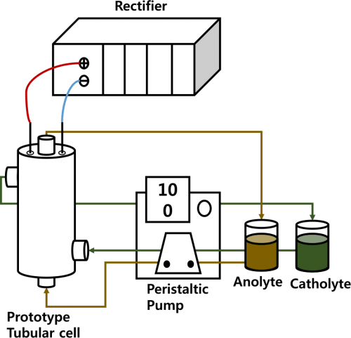 Figure 1. Schematic diagram of the Na-β-Al2O3 membrane and prototype experimental setup for the N-ARFB.
Charge-discharge cycling
The charge-discharge tests were conducted using a prototype tubular (made using Teflon material) Na-β-Al2O3-divided flow cell assembly with 0.1 M V(acac)3 and 0.1 M TBAP or NaClO4 in AN, as shown in Fig. 1. Two electrolyte tanks attached to each side of the prototype tubular cell were filled with 200 mL of the electrolyte. The graphite electrodes with a geometrical working area of 140 cm2 at a 0.5 cm distance were mounted, and separated by a Na-β-Al2O3 membrane. Peristaltic pumps (Masterflex) were used to circulate the electrolyte through the flow cell at a rate of 100 mL min−1. The graphite electrodes and membranes were cleaned sequentially by sonication in 0.1 M HNO3 and diethyl ether solution, rinsed thoroughly with the respective solvents, and dried overnight under vacuum. Prior to use, the electrodes and membranes were conditioned, as described previously, by soaking in a 0.1 M electrolyte solution for at least 4 h.10
Analysis
The migration of the V(acac)3 via Na-β-Al2O3 was measured primarily during charging and discharging separately by UV-visible spectroscopy using a Scinco s-3100 spectrophotometer. A 5 ml sample withdrawn from the cathodic (charging) or anodic (discharging) compartment at the desired time interval and analyzed by UV-visible spectroscopy to identify the migrated concentration of vanadium ions using a plot of standard vanadium concentrations. Scanning electron microscopy (SEM) and energy dispersive X-ray spectroscopy (EDS) of a used Na-β-Al2O3 piece taken from a tailor made electrolysis setup was performed using a Zeiss EVO- MA10, and the membrane surface morphologies were investigated.
Results and Discussion
Na-β-Al2O3 membrane suitability by electrochemical analysis
To check the suitability of Na-β-Al2O3 in the N-AVRFB system, resistance analysis was performed by electrochemical impedance analysis (EIS) and the results are shown in Fig. 2. The Nyquist plot was obtained for 0.01 M V(acac)3 in the presence of 0.1 M NaClO4 solution in AN with (Fig. 2A curve a) and without (Fig. 2A curve b) the Na-β-Al2O3 membrane. The difference in solution resistance (derived by an instant fit with an error % below 15) between with and without a membrane was 5.383 Ω cm2, which is considered to be the Na-β-Al2O3 membrane resistance (Eq. 2). By combining the thickness of the membrane with the obtained membrane resistance, an ionic conductivity of 2.97 × 10⁻² S cm−1 was derived using Eq. 1. The obtained ionic conductivity is comparable to the literature value (1.2 × 10⁻² S cm−1)24 obtained in biphenyl and dimethoxyethane-dissolved sodium. EIS of V(acac)3 dissolved in a 0.1 M TBAP electrolyte in AN was compared to determine the suitability of the Na-β-Al2O3 membrane, as shown in Fig. 2B. The Na-β-Al2O3 membrane in a 0.1 TBAP supporting electrolyte showed a slightly elongated semicircle with an increased resistance (Fig. 2B curve b) of 12.881 Ω cm2, which suggests that the charge carrier could be via a standard vacancy mechanism or correlated movement of interstitial Na+ ion pairs25 or the charge balance might have occurred by size exclusion. At the same time, the cell potential between the divided (by Na-β-Al2O3) and undivided cell containing the 0.1 M NaClO4 supporting electrolyte in AN showed a noticeable difference. The cell potential for the undivided cell reached 8 V by an applied current density of 1.7 mA cm−2 but in the divided cell, the cell potential reached 8 V with a 0.03 mA cm−2 current density. Many polymeric membranes are capable of use up to an applied current density of 40 mA cm−2 with a potential range of approximately 4 V for charging/discharging in N-ARFB.13 On the other hand, electrolysis in non-aqueous or ionic liquid medium leads to a high cell potential at the applied current density, galvanostatic mode, of below 10 mA cm−2.26,27 This could be due to the attainment of a solvent polarization limit. The present results obtained using the Na-β-Al2O3 membrane strongly correlated with not only the results of galvanostatic mode electrolysis in the non-aqueous medium electrolysis potential, but also many polymeric membranes in N-ARFB system worked in this applied current density region (0.004 to 0.01 mA cm−2).28–30
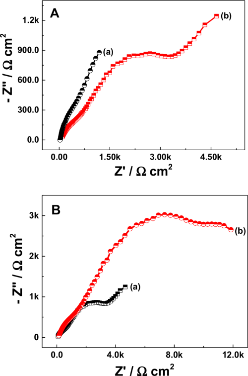
Figure 2. (A) Nyquist plot for the Na-β-Al2O3 conductance measurement with (a) and without (b) the membrane. EIS conditions: 0.01 M V(acac)3 with 0.1 M NaClO4 in AN solution at 0.5 cm gap between the membrane and electrodes. (B) Nyquist plot showing the effect of the electrolyte (a) 0.1 M NaClO4 and (b) 0.1 M TBAP on Na-β-Al2O3 membrane in a 0.01 M V(acac)3 solution in AN.
The cell potential variation may have also been influenced by the reversibility of the redox active species under the given electrolytic conditions. In the N-ARFB system, tetra ethylammonium tetrafluoroborate (TEAB) showed the maximum suitability, particularly on reversibility, than the other electrolytes due to the small radii and high limiting oxidation potential.31 In the present work, the cyclic voltammetry (CV) behavior of V(acac)3 using the Na-β-Al2O3 membrane-divided electrochemical cell in 0.1 M tetra butylammonium perchlorate (TBAP) and NaClO4 in AN at the glassy carbon (GC) electrode were compared, as shown in Fig. 3. In the 0.1 M TBAP electrolyte, a redox peak at approximately −1.50 V and −1.34 V vs. Ag/Ag+ was observed (Fig. 3 curve a), which was approximately 100 mV higher than the value reported for V(III) to V(II) reduction.10 Other redox peaks at approximately 0.85 V and 0.69 V vs. Ag/Ag+ was approximately 100 mV higher than the values reported for V(III) to V(IV) and an additional reduction peak at −0.66 V vs. Ag/Ag+ related to intermediate vanadium species.32,33 In contrast, the CV behavior of V(acac)3 in the 0.1 M NaClO4 electrolyte showed only two redox couples related to V(III) to V(II) (−1.40 V and −1.24 V vs. Ag/Ag+) and V(III) to V(IV) (0.76 V and 0.58 V vs. Ag/Ag+) (Fig. 3 curve b) with intermediate vanadium (−0.73 V) formation (Fig. 3 curve b). Note that highly reversible redox couples were recorded for V(acac)3 in the presence of tetraethylammonium hexafluoro phosphate (TEAPF6) or TEAB supporting electrolyte in AN on a GC electrode.5,7 On the other hand, the two vanadium redox couples exhibited quasi-reversible behavior under these given conditions, particularly in the TBAP and NaClO4-supporting electrolytes. In addition, the V(acac)3 redox behavior varied according to the supporting electrolyte used,31 which means that V(acac)3 shows sluggish electron transfer in the both the TBAP and NaClO4 supporting electrolytes, which might have influenced the cell potential variations. Importantly, the redox peak potentials in the presence of the NaClO4 supporting electrolyte was 100 mV less than the TBAP supporting electrolyte, either in the oxidation or reduction region, support that the NaClO4 supporting electrolyte facilitates the V(acac)3 redox process.

Figure 3. Cyclic voltammetry of a V(acac)3 solution in AN recorded at 50 mV s−1 at the GC electrode under different conditions. (a) with Na-β-Al2O3 in 0.1 M TBAP; (b) with Na-β-Al2O3 in 0.1 NaClO4.
Vanadium migration analysis
In many polymeric membrane-divided RFB systems, capacitive decay is a major setback of the cell performance4,10,34 due to the permeation of redox active species that leads to self-decay. In the present study, the migration of V(acac)3 through Na-β-Al2O3 was monitored during charging and discharging by UV-visible spectroscopy at defined electrolysis time intervals, as shown in Fig. 4. The V(acac)3 or V(acac)2 absorbance occurs at approximately 650 and 800 nm, respectively,35,36 which was used to determine its concentration in the cell during charging or discharging (Fig. 4A curve a). During charging, the cathodic compartment containing a 0.1 M NaClO4 solution in AN showed no peaks (expected the V(aca)3 ion migration from the anodic half-cell), which are related to vanadium ions (Fig. 4A curve b). This was confirmed by the different charging timings (inset figure in Fig. 4A), where no change in the UV-visible absorbance peak was observed until 4 h charging. In a similar manner, V(acac)3 migration was monitored during discharge (cathodic to anodic half-cell) (Fig. 4B), where also no peak related to the vanadium species was observed (Fig. 4B curve b) in the anodic half-cell and with discharging timings up to 4 h (inset figure of Fig. 4B), which confirms that the Na-β-Al2O3 will minimize the capacitive decay through the migration of redox active species, here vanadium. Furthermore, SEM analysis of the Na-β-Al2O3 before (Fig. 5a) and after (Fig. 5b) the charging/discharging experiments showed no prominent change in the membrane surface. EDS analysis of the before and after experiments, particularly for the Na ion atomic % showed a slight increase (4.69%) compared to the before electrolysis sample (4.56%), which suggests that Na+ ions are not leaching out. The slight increase in the Na ion % could be due the use of NaClO4 as an electrolyte, which might have helped the Na ions become intact or remain in the membrane. Overall, Na-β-Al2O3 can be used as a membrane in N-ARFB with a suitable electrolyte.
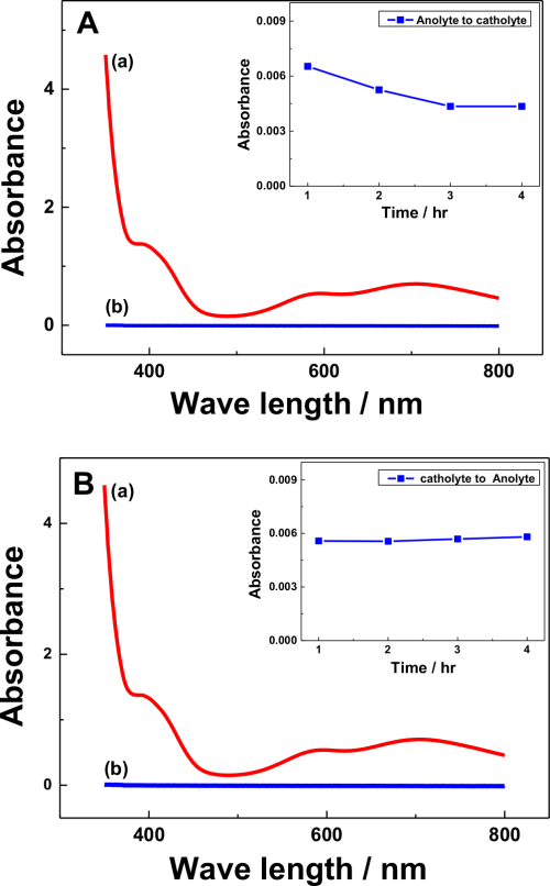
Figure 4. (A) UV-Visible absorption spectra of 0.01 M V(acac)3 in AN (a) and solution of cathodic half-cell after 1 h charging process (b). The inset shows the absorbance of cathodic half-cell solution during different charging timings (B) UV-Visible spectrum of the anodic half-cell solution (0.1 M NaClO4 in AN) after the 1 h discharging process (cathodic half-cell contains 0.01 M V(acac)3 +0.1 M NaClO4 in AN). The inset shows the absorbance of the anodic half-cell solution during different discharging timings. Conditions: Carbon felt electrodes with a geometric surface area of 2 cm2; applied current density of 0.01 mA cm−2; 250 ml (each half-cell) of electrolyte.
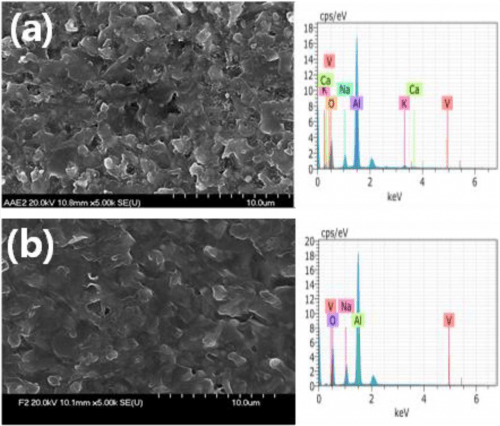
Figure 5. SEM images of Na-β-Al2O3 before (a) and after (b) charging/discharging experiments for N-ARFB. Conditions: Carbon felt electrodes with a geometric surface area of 2 cm2; applied current density of 0.01 mA cm−2; 250 mL (each half-cell) of 0.01 M V(acac)3 in AN.
Charging/discharging analysis
Fig. 6A shows the typical charge (V3+ oxidation-reduction) and discharge (V4+ reduction-V2+ oxidation) potential limits with time at a Na-β-Al2O3 tubular membrane-divided prototype electrochemical cell using a graphite electrode pair in AN electrolyte. The charging potential (upper limit) at first cycle reached 2.2 V and remained relatively constant up to 4 hr. From then, the discharge process was initiated with different cell potentials around 0.85 V and ended at 0.3 V in 4 hr. without a prominent discharging plateau. Similar charging discharging trend with increase in upper potential limit up to 3.3 V was observed in the first six cycles and remain constant in remaining all cycles. The interesting point here is the cell potential limits. The upper and lower limits reached 3.6 V and 0.85 V, respectively, which may be due to the ohmic or IR resistance of the electrochemical cell due to the electrolyte, electrode, and membrane resistance. V(acac)3 at the H-type cell showed a charging and discharging potential of 2.75 V and 0.4 V, respectively, where the discharge potential difference was affected by the electrode distance.7,37 Similar H-type cells used for the Mn(acac)3 and Cr(acac)3 redox flow battery in AN showed a huge potential difference between charging and discharging, including ohmic and IR resistance, according to electrode distance.38,39 Another possibility could be the dissociation of the V(acac)3 complex to V(acac)2 or the formation of a V(V) oxidation state or vanadium crossover.7 A recent study of V(acac)3 in AN with a zero gap (electrodes to membrane) showed a minimized charging and discharging potential of almost 0.2 V10 showing that the charging discharging potential difference is due mainly to the electrode distance. In addition, the membrane thickness affects the charging discharging cell potential and columbic efficiency reduction by 15%.7 As shown in Fig. 2 and Fig. 4, the lower membrane resistance and no crossover of V(acac)3 leads to an electrode distance or electrode for a high charging discharging potential difference. Further, no capacity decay was found while charging and discharging using the prototype tubular cell (Fig. 6B), though the capacity values found less (4.5 mA h g−1), confirms no crossover of V(acac)3 ions through Na-β-Al2O3 membrane. The calculated voltage and current efficiency for the above second cycle were approximately 16% and 11%, respectively, at the 15% state of charge. Some current loss might occur by complex dissociation and electrode distance but these can be rectified under optimized conditions.
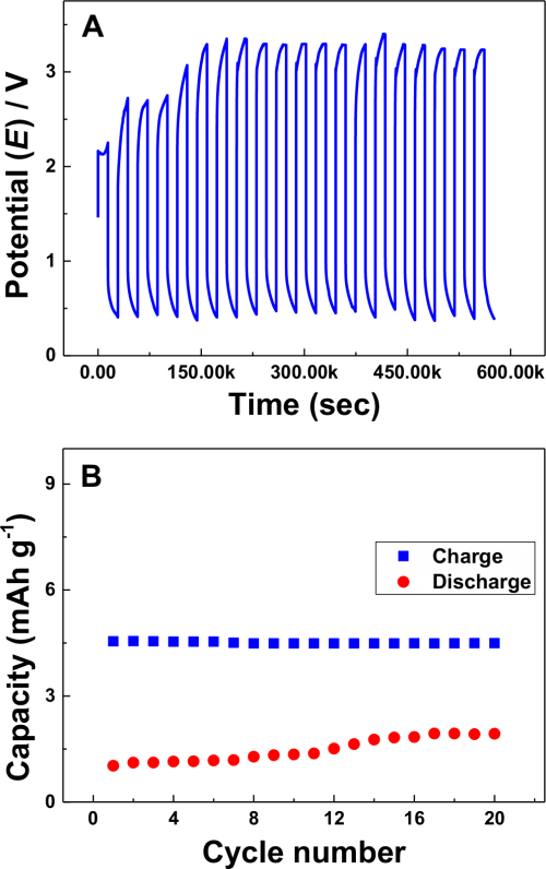
Figure 6. (A) Charge-Discharge curve and (B) Charge-Discharge capacity of 0.01 M V(acac)3 in 0.1 M NaClO4 in AN solution with charge and discharge current densities of 0.01 mA cm−2 and 0.0015 mA cm−2. 15% state of charge.
Conclusions
The Na-β-Al2O3 tubular membrane was applied successfully to the all-vanadium N-ARFB system through a prototype RFB cell. EIS confirmed that the ionic conductivity of the Na-β-Al2O3 membrane in the presence of 0.1 M NaClO4 in AN was 2.97 × 10⁻² S cm−1, which assisted in the development of a N-ARFB. The redox couples, V3+/V4+ and V3+/V2+, are quasi-reversible under the given conditions. UV-visible analysis during the charging and discharging of V(acac)3 confirmed that the lack of crossover through the Na-β-Al2O3 membrane can minimize the capacity loss. In addition, no definite change in the Na-β-Al2O3 membrane confirmed its stability toward long term operation. The high charging and discharging potential difference might be related to the electrode distance and quasi-reversible redox couples of V3+/V4+ and V3+/V2+, respectively, under the given conditions. The charging discharging cycle with approximately 16% voltage efficiency and 11% current efficiency at the 15% state of charge highlight the potential of the Na-β-Al2O3 membrane.